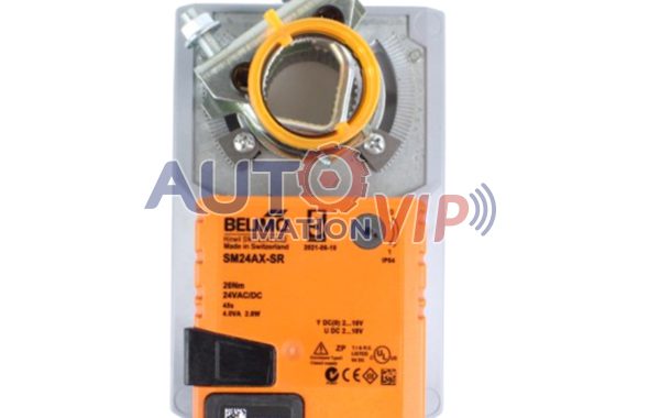
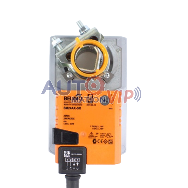
Schärer-Elektronik AG, Trip Circuit Control Relay, TSG912X22L22, TSG912N11L11

TSG 912 X22 L22, TSG 912 N11 L11 Schärer-Elektronik AG Trip Circuit Control Relay New Arrival

TRIP CIRCUIT SUPERVISION RELAY TSG 912
The Type TSG 912 relay supervises the trip circuit ofcircuit breaker andit activates delayed alarm and visual indication in the event of trip cir-cuit failure or mechanism malfunction.
The relays are available for allkinds of circuit breakers and for any combination of standard trip andalarm voltages.

Schärer-Elektronik AG, Trip Circuit Control Relay, TSG912X22L22, TSG912N11L11

Schärer-Elektronik AG, Trip Circuit Control Relay, TSG912X22L22, TSG912N11L11

New arrivals this month: TSG 912 X22 L22, TSG 912 N11 L11. Welcome to order from automationvip.com.

MCUP-50 S.C.EXPORTS.S.R.L Cooling Water Pump‌

MCUP-50 S.C.EXPORTS.S.R.L Cooling Water Pump‌ in stock

The ‌MCUP-50 S.C.EXPORTS.S.R.L Cooling Water Pump‌ is a specialized industrial pump designed for efficient cooling water circulation. Below is a structured overview based on available technical and commercial specifications:

MCUP-50 S.C.EXPORTS.S.R.L Cooling Water Pump‌

MCUP-50 S.C.EXPORTS.S.R.L Cooling Water Pump‌

Product Overview‌
‌Manufacturer‌: S.C.EXPORTS.S.R.L, a company associated with industrial fluid-handling solutions.
‌Model‌: MCUP-50, available in multiple voltage configurations (e.g., 220V, 230V, 380V).
‌Primary Function‌: Transfers cooling water to industrial equipment, power plants, or HVAC systems to regulate temperature and ensure stable operations.

Applications‌
Industrial cooling systems (e.g., machinery, reactors).
Power plant cooling circuits.
HVAC and large-scale air-conditioning units.
Compatible with water, emulsified liquids, and mildly corrosive fluids

MCUP-50 S.C.EXPORTS.S.R.L Cooling Water Pump‌ 220V 380V products are in stock. If you need to order, please contact us.


CEIA Metal Detectors, PD140E, PD140N

CEIA PD140E Security Metal Detector: High Sensitivity, Durability, and Ergonomic Design‌

‌CEIA PD140E Security Metal Detector Technical Specifications and Performance Features‌

‌Battery Life‌: Operates continuously for over 100 hours using AA alkaline batteries, with a low battery indicator.
‌Operating Temperature Range‌: -40°C to 70°C, storage temperature of -40°C to 80°C, and relative humidity tolerance of 0–98% (non-condensing).
‌Dimensions and Weight‌: Compact size of 360mm × 80mm × 40mm, lightweight at 390g (including batteries).
‌Material‌: Constructed from gray shock-resistant technopolymer for enhanced durability.

CEIA Metal Detectors, PD140E, PD140N

CEIA Metal Detectors, PD140E, PD140N

‌Design and Functional Highlights‌

‌Ergonomic Design‌: Features a unique offset handle to minimize scanning effort and reduce detection time.
‌Fully Digital Architecture‌: Utilizes advanced plastic materials for a sleek, rugged, and modern design.
‌Sensitivity and Detection Capability‌: High-precision detection of unconventional metal objects, compliant with the latest security standards.
‌Alert Modes‌: Combines visual, audible (75dB buzzer), and vibration alarms with three adjustable sensitivity levels.

‌Applications‌

The PD140E CEIA is ideal for high-security environments requiring reliable metal detection, including:

Security checkpoints at airports, train stations, and public venues.
Critical infrastructure such as nuclear facilities and government buildings.
Cultural heritage sites like museums and historical monuments.

‌Availability‌

CEIA PD140E Currently available in stock. For procurement inquiries, suppliers can contact us for the most competitive pricing.

RTA PAVIA X-PLUS B4 Stepping Motor Driver

X-PLUS B4 PLUS B4 RTA PAVIA Stepping Motor Drive in Stock

RTA PAVIA Stepping motor drive X-PLUS B4 Introduction

RTA PAVIA Driver, X-PLUS B4, RTA PAVIA Stepping Motor Driver

RTA PAVIA Driver, X-PLUS B4, RTA PAVIA Stepping Motor Driver

RTA PAVIA X-PLUS B4 Stepping Motor Driver

RTA PAVIA X-PLUS B4 Stepping Motor Driver

► Stepping motor drives series with Step & Direction interface and direct input from the main AC power supply (from 110 VAC to 230 VAC).
► The drive is equipped with an internal rectifier able to transfer more than 330 VDC (230 VAC) to the motor, in order to ensure the maximum power for the application as well as a significant cost saving on transformer and rectifier, together with the related cabling.
► Target: advanced application requiring great dynamic performance, high reliability and semplified power supply.

HIGHLIGHTS

► Microstepping function up to 4.000 step/rev.
► Connection directly to the main AC supply (110 to 230 VAC) normally avoiding the need for a transformer.
► Electronic damping facility for further acoustic noise and mechanic vibrations reduction at low and medium speed.
► External fans not needed: ideal both for mounting inside a metallic electrical cabinet and for stand-alone applications.
► Optoinsulated and differential input and output signals ease interfacing with the most commonly used control systems and ensure high noise immunity.
► Coupling with stepping motors rated for high voltage and equivalent or bigger than NEMA 34 is mandatory.

TECHNICAL SPECIFICATIONS

► Version: drive housed in a metallic box 152 x 129 x 46 mm, equipped with plug-in connectors.
► Range of operating voltages: 110-230 VAC.
► Range of current: 2.4-4 Amp. Easy setting of values by means of dip-switch.
► Microstepping: 400, 500, 800, 1.000, 1.600, 2.000, 3.200 and 4.000 steps/revolution. Setting by means of dip-switch.
► Automatic current reduction at motor standstill.
► Protections:
-Protection against under-voltage and over-voltage.
-Protection against a short-circuit at motor outputs.
-Overtemperature protection with thermal sensor.
► Optoinsulated inputs compatible with differential control signals.
► Possibility to switch off motor current with an external logic signal.
► High efficiency CHOPPER with IGBT final stage output.
► Electronic resonance damping circuit to ensure acoustic noise and mechanic vibrations reduction at low and medium speed.
► Alarm memory by use of yellow blinking led.
► External fans not needed.
► Coupling with stepping motors rated for high voltage and equivalent or bigger than NEMA 34 is mandatory.
► Warranty: 24 months.

RTA PAVIA Stepping Motor Drive X-PLUS B4 Details
( 110 – 230 VAC 2.4 – 4.0 Amp ) with Plug_in connectors


Microprecision Switches, MP321SEB01D, MP320, MP321

Microprecision Micro Switches: High Protection & Longevity for Demanding Environments

‌Microprecision Micro Switches: Delivering Precision and Reliability for Intelligent Elevator Control Systems‌

Microprecision Switches, MP321SEB01D, MP320, MP321

Microprecision Switches, MP321SEB01D, MP320, MP321

As a global benchmark in precision control technology, Microprecision Electronics SA provides efficient and robust solutions for the elevator industry through innovative micro switch technology. Our products are trusted by international industry leaders such as Otis, Schindler, and SEW-Eurodrive.

‌Core Value: Precision Control × Long-Term Safety‌

‌1. Millimeter-Level Precision Control‌

Proprietary micro-differential stroke technology (<0.05mm actuation travel) ensures precise detection of brake air gaps, enabling customers to:
✓ Reduce braking noise by over 30%
✓ Decrease braking energy consumption
✓ Optimize electromagnetic brake response speed

‌2. Full-Scenario Environmental Adaptability‌

Wide temperature range design (-40°C to +85°C) for stable operation in extreme conditions
IP67 protection rating: dustproof, waterproof, and vibration-resistant
Extended mechanical lifespan (10+ million cycles) reduces maintenance costs

‌Three Core Application Scenarios‌

▶ Intelligent Elevator Brake Control‌
✓ Hermetic structure prevents dust infiltration
✓ Real-time brake status monitoring to prevent idling risks
✓ Compliant with EN/UL/CSA international certifications

▶ Cabin & Door Limit Protection‌
✓ 8 actuator configurations for flexible adaptation to diverse models
✓ Multiple cable specifications simplify installation
✓ Instant safety signal triggering prevents entrapment accidents

▶ Energy-Saving & Noise Reduction Optimization‌
✓ Micro-differential stroke technology minimizes brake gaps and operational noise
✓ Reduced ineffective friction extends brake lifespan by 30%


VOITH H+L Solenoid Valve, WE02-4L100R24/0H, WE50-4R1440R24/0H

New Arrived: VOITH H+L WE02-4L100R24/0H Solenoid Valve

We are excited to announce the arrival of the ‌WE02-4L100R24/0H‌, a state-of-the-art solenoid-operated control valve designed to deliver exceptional precision in demanding industrial applications. Engineered for versatility and performance, this 24V DC-powered valve combines compact design with advanced functionality, making it an ideal solution for systems requiring meticulous flow regulation.


VOITH H+L Solenoid Valve, WE02-4L100R24/0H, WE50-4R1440R24/0H

VOITH H+L Solenoid Valve, WE02-4L100R24/0H, WE50-4R1440R24/0H

Key Benefits:‌

‌Compact Design‌: Ideal for installations with limited space.
‌24V DC Operation‌: Energy-efficient and compatible with standard automation systems.
‌Precision Performance‌: Perfect for CNC machinery, industrial hydraulics, and automation requiring meticulous flow adjustment.

‌Applications:‌

CNC machine tools
Hydraulic presses and lifts
Automated production lines
Upgrade your systems with the WE02-4L100R24/0H for enhanced efficiency and accuracy. Contact us to order or learn more!

PN 10600001 RECO Solenoid Valve

Common Failures and Troubleshooting Methods for RECO Solenoid Valves

The common failures and troubleshooting methods for RECO solenoid valves (Germany) include the following:

‌1. Coil Short Circuit or Open Circuit‌

Use a multimeter to measure the continuity of the solenoid valve coil. If the resistance approaches zero or infinity, the coil is short-circuited or open-circuited.
If the resistance is normal but the valve still fails to activate, perform a final test: Place a small screwdriver near the coil’s metal rod and power on the valve. If no magnetic force is detected, the coil is damaged and must be replaced.

‌2. Wiring Issues‌

Check for loose or disconnected wiring terminals and tighten them if necessary.
If the valve does not activate, disconnect the wiring and use a multimeter to test for an open circuit in the coil. If confirmed, the coil is burned out and requires replacement.‌

3. Valve Core Failure‌

If the valve shows no response under normal media pressure, the valve core may be damaged.
Inspect for impurities or moisture in the media. If cleaning the media does not resolve the issue, replace the valve core or the entire solenoid valve.

‌4. Sticking Issues‌

The sliding sleeve and valve core have a minimal gap, making them prone to jamming due to debris or insufficient lubrication.
Temporary fix: Insert a thin wire into the valve’s front hole to manually dislodge the core.
Permanent solution: Disassemble the valve, clean the core and sleeve thoroughly, and ensure smooth movement.

‌5. Air Leakage‌

Air leaks reduce pressure, hindering valve operation. Causes include damaged seals or worn sliding components.
Address leaks when the valve is de-energized. Replace sealing gaskets or repair/replace the sliding components as needed.

‌6. Abnormal Noise‌

Noise during operation may stem from foreign objects in the pilot valve or loose nuts.
Solution: Clean the pilot valve and tighten all fasteners.

‌7. Valve Jamming‌

Caused by debris or insufficient lubrication.
Solution: Clean the valve and apply appropriate lubricant.

‌8. Gas Leakage‌

Leaks occur due to damaged seals or worn sliding parts.
Solution: Replace sealing gaskets or repair/replace the sliding components.

‌9. Slow Response‌

Delayed action may result from debris in the valve or pilot valve.
Solution: Clean the affected components.

‌10. Abnormal Flow Rate‌

Caused by partially opened diaphragms or pilot valve issues.
Solution: Clean or replace the pilot valve and ensure the diaphragm moves freely.

PN 10600001 RECO Solenoid Valve

This guide provides systematic steps to diagnose and resolve common issues with RECO solenoid valves, ensuring optimal performance and longevity.

‌Maintenance and Servicing of Encoders‌

Proper maintenance and servicing of encoders require adherence to specific methods and precautions. The detailed guidelines are as follows:

‌Servicing Methods‌

‌Cable Issues‌

‌Symptoms‌: Broken wires, short circuits, or poor contact.
‌Procedure‌:
Inspect the cable for visible damage (e.g., cracks, breaks). Replace the cable if damaged.
For loose connectors, re-plug or replace the connector.
Ensure the cable is securely fastened to prevent loose connections or soldering failures.

‌Power Supply Issues‌

‌Symptoms‌: +5V power drops below 4.75V.
‌Procedure‌:
Check the power supply for faults (e.g., damaged power modules). Repair or replace faulty components.
Inspect power transmission cables. Replace cables with excessive resistance to reduce power loss.

‌Battery Issues (Absolute Encoders)‌

‌Symptoms‌: Low battery voltage (often accompanied by alarms) or loss of reference point memory.
‌Procedure‌:
Replace the battery promptly.
Perform a reference point reset if the reference position is lost.

‌Shield Wire Issues‌

‌Symptoms‌: Unstable waveforms or communication errors due to missing or detached shielding.
‌Procedure‌:
Reliably solder and ground the shield wire to ensure effective shielding.

‌Loose Installation‌

‌Symptoms‌: Position control inaccuracies, servo overload alarms.
‌Procedure‌:
Reinstall the encoder securely.
Inspect the mounting bracket for damage and replace if necessary.

‌Optical Grating Contamination‌

‌Symptoms‌: Reduced signal output amplitude.
‌Procedure‌:
Gently clean oil or debris from the grating with lint-free cotton soaked in alcohol. Avoid scratching the grating.

‌Internal Component Failure‌

‌Symptoms‌: Damaged sensors, circuit boards, or other internal parts.
‌Procedure‌:
Only qualified personnel should disassemble the encoder and replace faulty components.
‌Caution‌: Unauthorized disassembly may cause irreversible damage.

‌Maintenance Guidelines‌

‌Regular Cleaning‌

Wipe the encoder housing with a soft cloth or compressed air to remove dust.
For optical components (e.g., gratings), use lint-free cotton and a specialized optical cleaning solution.

‌Inspect Installation and Connections‌

Monthly checks:
Ensure mounting bolts and connectors are secure.
Inspect cable connectors for oxidation or corrosion. Address issues promptly.
‌Avoid Environmental Interference‌

Install encoders away from strong magnetic fields (e.g., motors, transformers, inverters).
Route signal and power cables separately to minimize electromagnetic interference.

‌Prevent Overload and Shock‌

Operate the encoder within specified load and speed limits to avoid mechanical stress.

‌Record Keeping‌

Maintain a maintenance log documenting inspections, cleaning, repairs, and outcomes. This aids in identifying potential issues and streamlining future troubleshooting.
By following these protocols, encoder performance and longevity can be significantly enhanced. For complex failures, always consult professional technicians.

WOODWARD MSC 401072-90 Magnetic Sensors Corporation VR Speed Sensor

Woodward 401072-90 (M16-1.5) MPU MSC Speed Sensor: A Reliable Solution for Marine Generator Sets

WOODWARD MSC 401072-90 Magnetic Sensors Corporation VR Speed Sensor

WOODWARD MSC 401072-90 Magnetic Sensors Corporation VR Speed Sensor

1. Genuine Quality Assurance

The Woodward 401072-90 (M16-1.5) MPU MSC speed sensor is a genuine product. Its original quality has been verified and meets the highest standards, ensuring reliability and performance in marine generator set engine applications.

2. Universal Compatibility

Designed for a wide range of marine generator set engines, this product serves as a universal solution for users. It is compatible with both 12v and 24v systems, providing flexibility in different electrical setups.

3. Durable Design

Constructed with high – quality materials, this speed sensor can withstand harsh marine environments. It offers long – lasting performance and requires minimal maintenance, making it a cost – effective choice for marine applications.

4. Easy Installation

The Woodward 401072 – 90 (M16 – 1.5) MPU MSC speed sensor features a compact design that allows for direct installation. This design minimizes downtime for users, enabling quick and hassle – free replacement or initial setup.

5. Comprehensive Support

As an authentic Woodward product, it comes with a comprehensive support system. This includes technical assistance and a warranty, ensuring that users can get timely help whenever they need it.